
|
Early consideration into the design of the RaceGauge yielded an intersting
engineering obstacle: How should this complicated, multi-module computer/car
system turn on and off? Clearly it would not be beneficial to leave the
RaceGauge constantly on (powered by the car bettery +12v), because the
battery would soon die. Also, it would not be wise to power the entire
system from the key ignition circuit, because that circuit was not designed
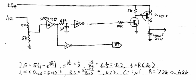
to provide large amounts of power. So an electronic switch was needed. Later analysis showed that a switch was not enough, because the HC11 MPU board needs time to shut down, in order to store the odometer readings on the non-volatile EEPROM memory. So a power-cycling circuit was designed and built on a small Radio Shack printed-circuit board. This circuit uses CMOS logic chips for minimum power consumption, because it must be constantly powered on. The Power Cycling board has two inputs: one from the constantly-on +12v line from the car battery, and another from the ignition switch. It also has two outputs: one goes to the main power supply board, which has a built-in electronic switch, and the other goes to the MPU board. When the ignition is turned off, the signal to the MPU board goes low, which signals an interrupt which stores the current odometer mileage. Several hundred milliseconds later, the output to the main power supply board goes low, which turns off the power to the RaceGauge system. The schematic for the power-cycling circuit and the timing analysis is shown below: |

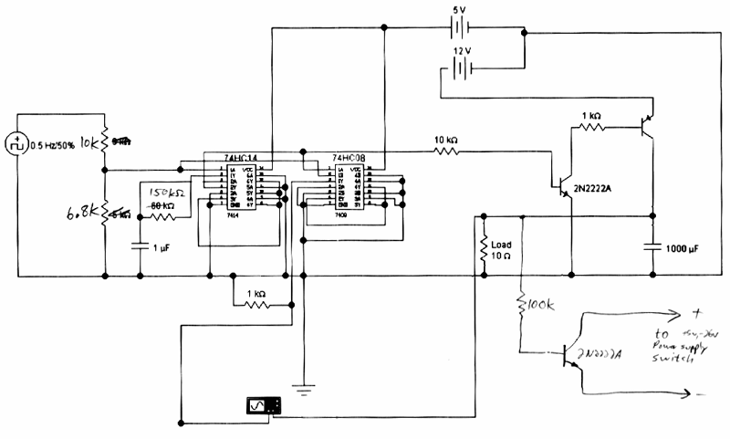
| The power cycling circuit was created and tested with Electronic Workbench 5.0 before being built on the PC board. The test schematic printout is shown below: |
