|
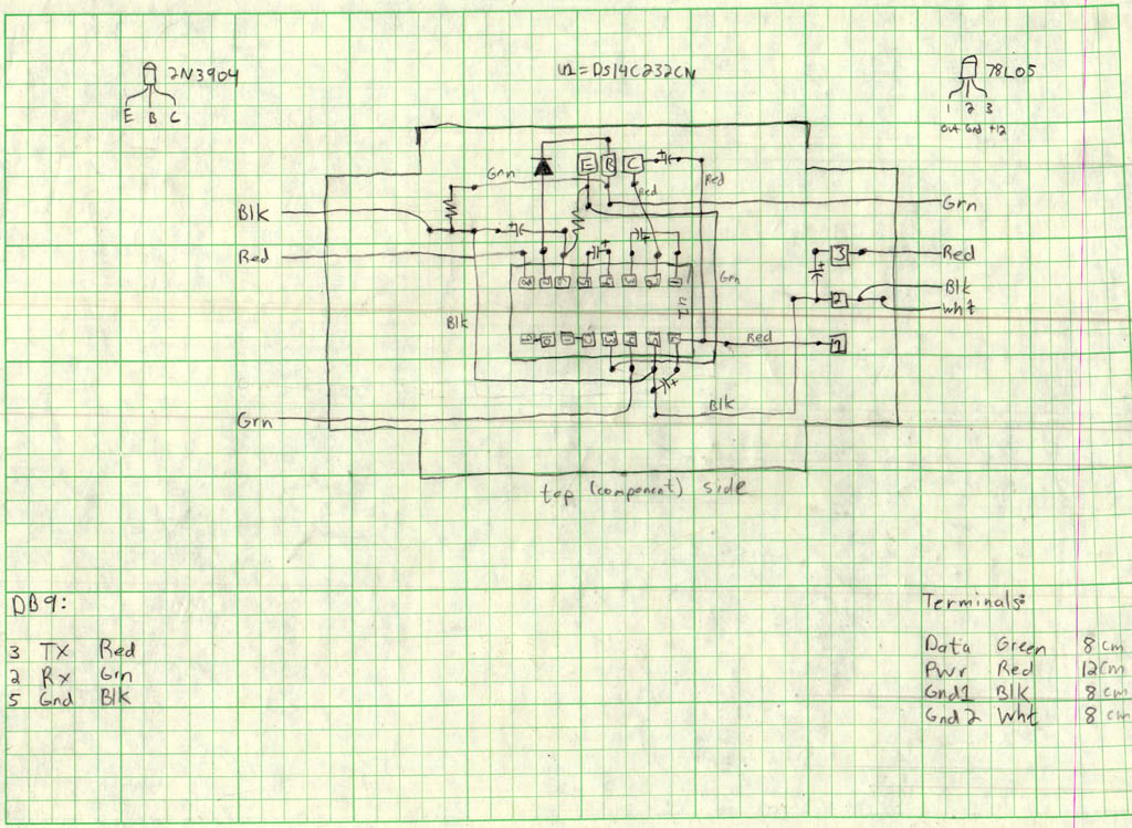
This is the circuit board layout for the Fascination Software design of this cable.
The circuit board is built to fit in the project box - they are available together
from Radio Shack as part number 270-283. Each square on the graph paper represents
a through hole on the circuit board. A black dot on this diagram represents a
component lead or wire soldered on the bottom. Everything is connected together by
solder on the bottom layer of the board. The lines going between adjacent squares
represent solder connections. There are a total of 7 jumper wires required, and
they are labeled with colors on this diagram(red, green, black).
I cut the 4-conductor wire (which connects this circuit board to the DB9 serial connector and quick disconnects) so that the end with the DB9 connector is 16 inches long, and the other end (that has quick-disconnects which plug into the ECU diagnostic port) is 80 inches long. |